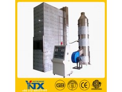
The bunched cable the combustion testing machine is a very mature product of our company, we all use double stainless steel machine is composed of the following parts: test chamber, air source, steel ladders, emissions purification system, the ignition source , implementation of standards GB/T18380.31-2008, IEC60332-3-10-2000 combustion test and optical fiber cables under fire conditions - Part 31: vertically-mounted bunched wires or cables flame vertical spread of the test report test device to meet GB/T18380.32-2008/IEC60332-3-21: 2000 "burning test and optical fiber cables under fire conditions - Part 32: vertically-mounted bunched wires or cables flame the vertical spread tests AF / R class", GB/T18380 .33-2008/IEC60332-3-22: 2000 "burning test and optical fiber cables under fire conditions - Part 33: vertically-mounted bunched wires or cables flame vertical spread test class A", GB/T18380.35-2008 / IEC60332-3-24: 2000 "burning test and optical fiber cables under fire conditions - Part 35: vertically-mounted bunched wires or cables flame vertical spread test Class C", GB/T18380.36-2008/IEC60332-3-25 : 2000 burning test and optical fiber cables under fire conditions Part 36: The vertically-mounted bunched wires or cables flame spread test Class D
1, the experimental device
1.1 chamber: experimental device is a wide (1000 ± 100) mm, depth (2000 ± 100) mm and high (4000 ± 100) mm self
Legislation cabinet, above ground Xiangdi. Surrounding the test chamber should be sealed, air distance from the bottom of the front wall (150 ± 10) mm opened at a
The (800 ± 20) mmX (400 ± 10) mm of the intake port into the box (see Figure 1). Should be open in the back of the box at the top of a (300 ± 30)
mm × (1000 ± 100) mm outlet. The back wall and both sides of the chamber of the heat transfer coefficient of about 0.7W ∙ m-2 ∙ K-1's hot absolute
Edge, 1.5mm thick USU304 stainless steel plate, the intermediate-coated 65mm thick insulation mineral fiber outside 1.5mm thick USU304 No
Stainless steel plate (Figure 2). The distance between the steel ladder with the test chamber back wall (150 ± 10) mm, steel ladder bottom have cross-file from the ground (400
± 5) mm. At the lowest point of the cable samples from the ground of about 100mm (see Figure 3)
1.2 Air source:
1.2.1 inlet port is equipped with the DRO air speed wind Susu meter, can be read visually and can control the flow of gas through the casing air (5000 ± 500), L / min. During the test, can stabilize the air flow rate .
One hour sample after the 1.2.2 test: If you stop for the fire still burning, has alarm and a rain forced stop burning device
1.3 steel ladder type: W (500 ± 5) mm wide standard steel ladders (800 ± 10) mm wide steel ladders material for USU304 stainless
1.4 emission purification material device:
The upper part of the 1.4.1 test chamber equipped with a digital anemometer ensure that the wind velocity is less than 8M / S, will not affect the air flow from the test chamber.
1.4.2 smoke collected and washed soot apparatus: SUS304 stainless steel, diameter of 800mm and height 3500mm see Fig.
1a. Smoke collection tower is divided into three parts: spray device, soot filtration devices, smoke device. Spray device: as a special filter material
The material provides a water spray to keep special filtering materials effectively filter the smoke. Soot filter means: drinking water filtration material was filtered,
Effective filter soot so exhaust smoke is white smoke, in full compliance with the requirements of environmental protection. Manual cleaning and replacement and offers two sets.
The exhaust device: equipped with a high-powered exhaust fan and install a gate can control the wind flow rate.
2, ignition sources
2.1 Type: ignition sources should include one or two with type propane gas torch and its supporting flowmeter and Venturi mixer. For the fire surface should be drilled (242) diameter of the 1.32mm aperture of the flat metal plate, the distance from the center of these holes is 3.2mm, staggered in three rows, each row 81,80, and 81 respectively, located in the nominal The size is within the range of 257 × 4.5mm. Further, on both sides of the Spitfire plate, a row of apertures each opening, these guide holes to maintain the stability of the flame combustion. (Burner shown in Figure 5a and Figure 5b; its pore distribution is shown in Figure 6)
Each burner should be equipped with accurate means to control the propane and air inflow rate. Rotameter or mass flow meter
The 2.2 ignition source location
The torch should be placed horizontally from the front surface of the cable sample (75 ± 5) mm from the bottom of the chamber (600 ± 5) mm, with steel ladders axis symmetry. The torch for the fire point should be located in the center between the the steel ladder two rungs, and at least 500mm away from the sample the lower end


